
What is UML?
Unified Modeling Language (UML)
The Unified Modeling Language (UML) was created to forge a common, semantically and syntactically rich visual modeling language for the architecture, design and implementation of complex software systems both structurally and behaviorally. UML has applications beyond software development, such as process flow in manufacturing.
It is a graphic language to visualize, specify, construct and document a system. UML offers a standard for describing a system (model), including conceptual aspects such as processes, system functions, and specific aspects such as expressions of programming languages, database schemas …
UML is not programming, only is diagrammed the reality of a use in a requirement.
UML has several types of diagrams, which show different aspects of the entities represented.
Types of UML diagrams
UML uses elements and associates them in different ways to form diagrams that represent static or structural aspects of a system, and behavior diagrams that capture the dynamic aspects of a system.
UML structural diagrams:
-
Class diagram.
-
Components diagram.
-
Structure diagram.
-
Implementation diagram.
-
Object diagram.
-
Package diagram.
UML behavioral diagrams:
-
Activity diagram.
-
Communication diagram.
-
Interaction diagram.
-
Sequence diagram.
-
State machine diagram.
-
Timing diagram.
-
Use case diagram.
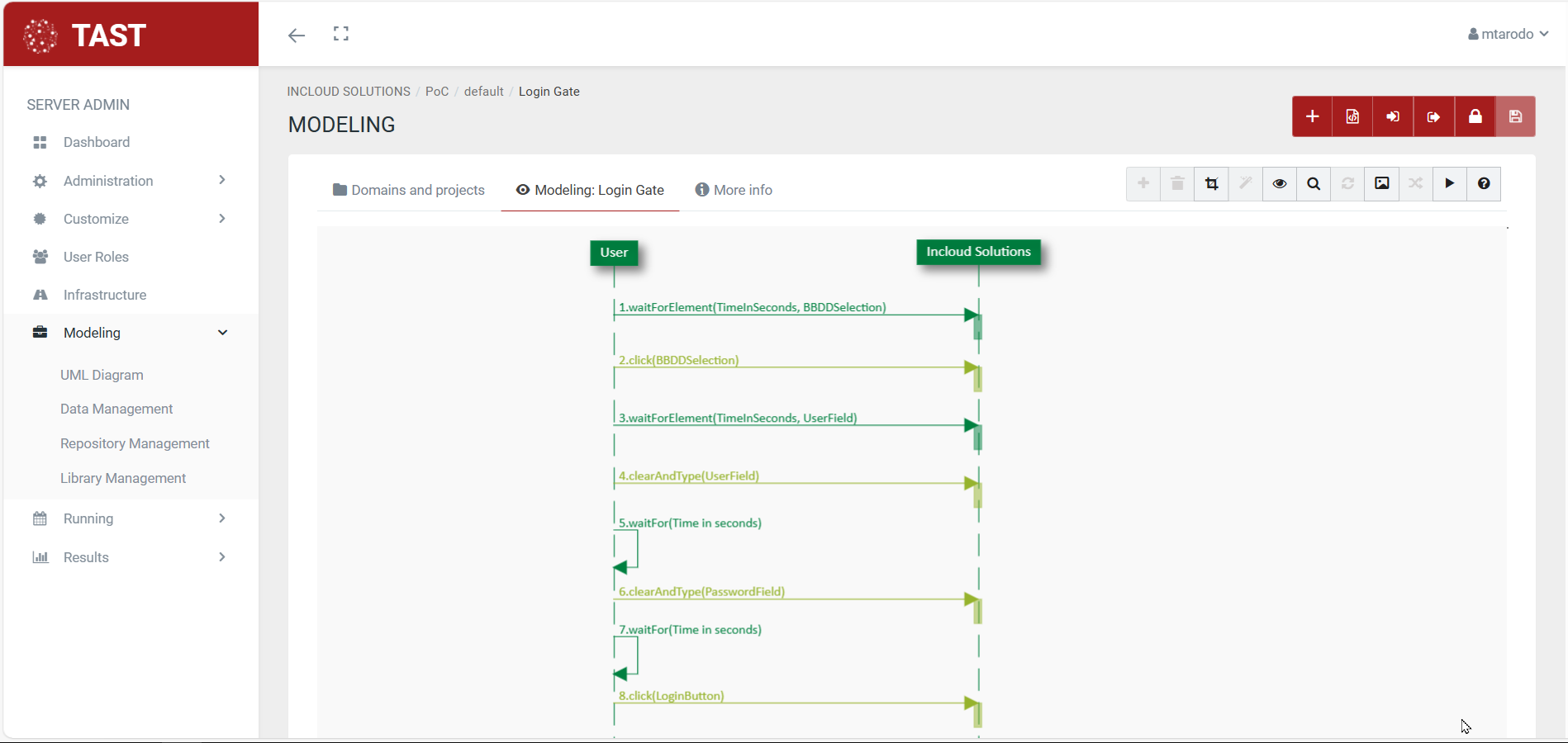
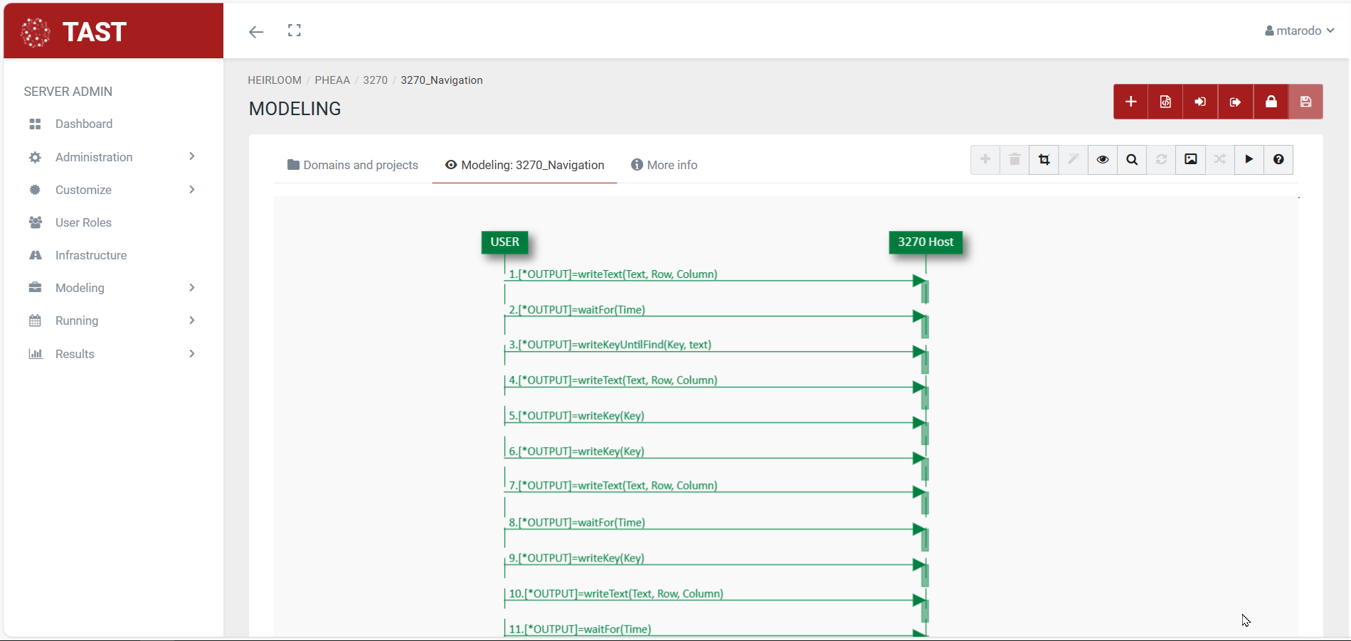
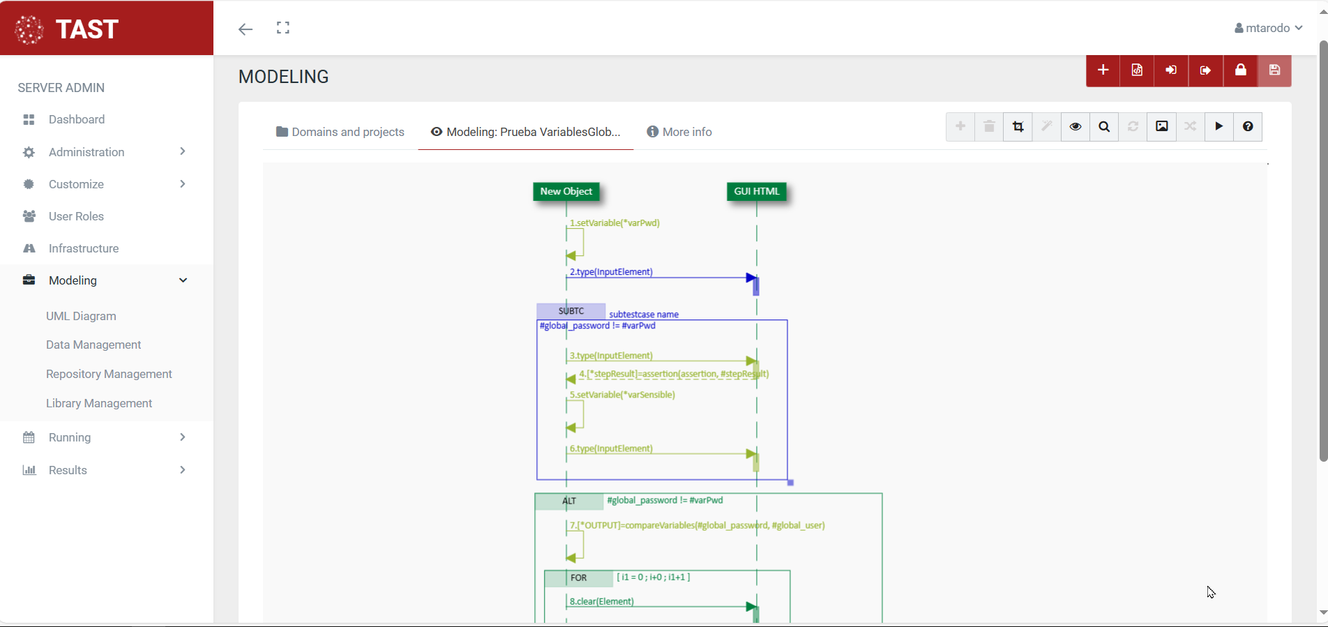
Sequence diagrams
A sequence diagram shows the interaction of a set of objects in an application over time and is modeled for each use case. Objects are the basic building blocks of UML diagrams and represent certain characteristics of a system element, which vary depending on the diagram. They describe how a group of objects work together and in what order they work together.
The sequence diagram contains details of the scenario implementation, including the objects that are used to implement the scenario and the messages exchanged between the objects.
Sequence diagrams are often used in software engineering to describe the interactions of objects within a system. They show how the different parts of that system interact with each other when a functionality is executed, and highlight the order in which these interactions should take place. Sequence diagrams use a vertical axis to mark time and a horizontal axis for objects.
As these diagrams represent timelines of events, they will start at the top and then gradually descend, marking consecutive sequences of interactions. Each object will have its own column, and all messages exchanged between objects will be represented by arrows. Branches, conditions and loops can be used in the sequence diagram.
Here are some examples of sequence diagrams:
No Comments